Generalized Grasping with Sawyer
Introduction
Grasping objects is one the central challenges of robotics, finding applications in nearly usage of robotics from industry to medicine. It is an active area of research, and considered an exceptionally difficult task in the field of Reinforcement Learning.
The application and reputation of grasping inspired us to form our own approach to the problem. The goal of our project was to design our own algorithm to detect, localize, and grasp general objects in a controlled environment. Through our design choices, we sought to maximize the set of objects we could grasp. To do this, we tackled problems of detecting general objects independent of shape and size, determining grasping angles, and controlling the end-affector to always grab the object without collisions. This led to an original implementation designed and implemented independently of similar research.
This project can be applied to any application requiring grasping of objects that cannot be determined beforehand. For example, it can be used for robot arms in industrial plants that need to move over several different objects, in emergency situations where rubble can take on any shape, or in medicine where there are hundreds of different tools.
Design
Implementation
Hardware
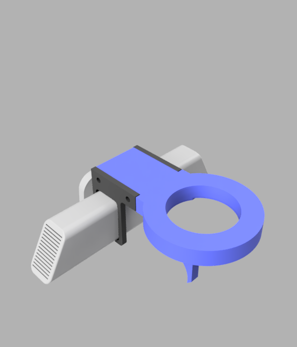
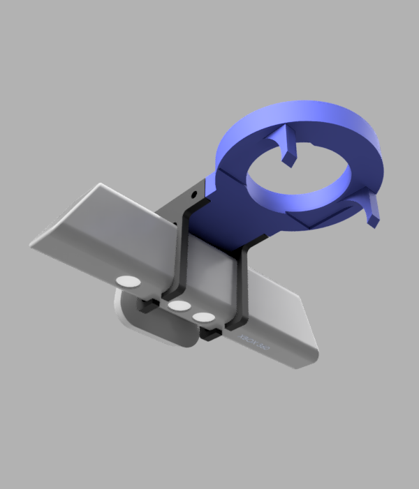
There are two primary components to our design, the blue cuff in the center of the image, and the two black clips which retain the Kinect sensor itself. These are bolted onto the blue cuff. All plastic parts were 3D printed, we used both the Cory Supernode and the Moffit Makerspace
We choose to design a cuff that sat around the metal wrist of Sawyer for a couple reasons. Firstly, we wanted to make installation and removal of our interface quick and easy, so avoiding more screws and bolts was appealing. Secondly, because the wire connecting the parallel gripper to Sawyer is very short, it would be challenging to slip an interface plate between the gripper and the arm, to say nothing of having to get new longer screws to screw the gripper on that would be long enough to pass through our interface. However, because we were no longer using screws, we faced the issue of keeping our interface in the same position for each round. We solved this using two techniques.
To try to constrain our interface rotationally, we started by simply designing the part to have close to a friction fit on the arm, which then let us add tape to the inside of the part, producing a good friction fit. Note the curved plastic arcs coming off the blue piece in the image, these were used to start the interface in the same position each time we installed the gripper. We would position the blue plastic piece in such a way around the cuff that one of the arcs would be in contact with the electric parallel gripper. Originally our hope was that these arcs would snugly fit around the curve in the gripper, but that proved too challenging to design and the friction-fit approach worked suitably well that we continued with that.
The black Kinect clips are designed to tightly fit around the Kinect, and are designed a few millimeters too thin in order to utilize the flexing of the plastic to keep the Kinect in position. Experimentally, they kept the Kinect from slipping even when held such that the Kinect opening was parallel to the floor
As a future extension, it would be good to change this part to one that is screwed onto the robot arm itself to increase repeatability of our approach. We made that tradeoff primarily for time reasons for this project, but a rigidly attached end effector would increase reliability and its disadvantages would be mitigate by not having to install and uninstall it frequently.
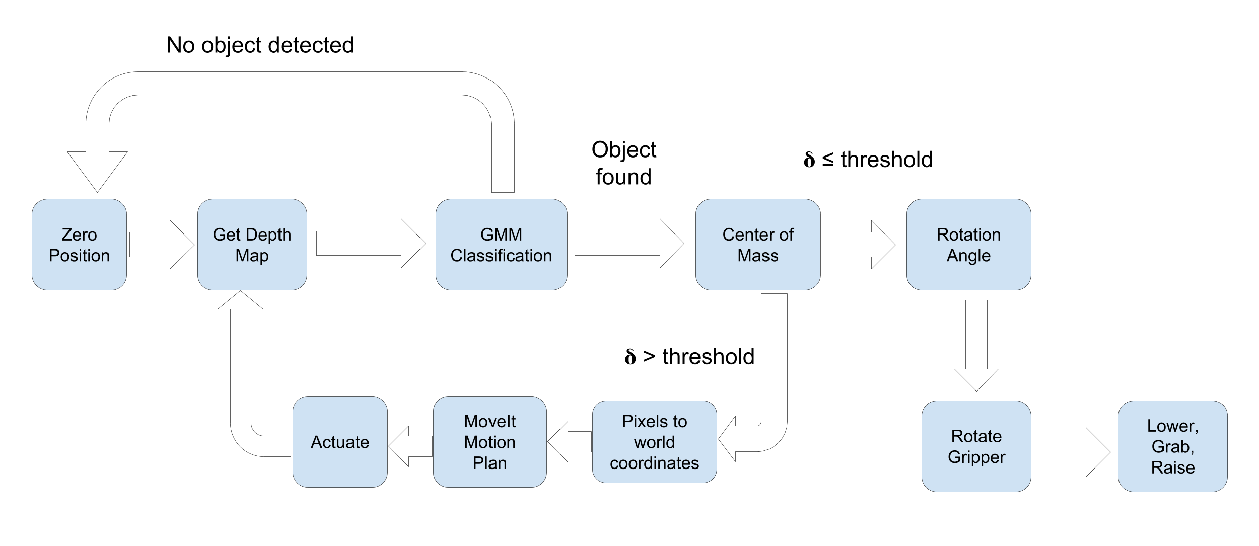
Image Pipeline
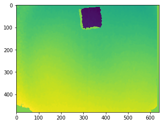
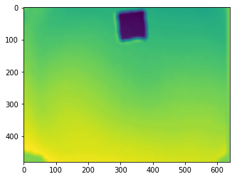
(1): Depth map of a box on a table. Solid green areas correspond to errored values.
Kinect Depth Map and Error Correction:
At the start of the loop, we collect a depth map of the area of interest from the Kinect using the Freenect library. The sensor from the Kinect is less than perfect. In addition to noise, the Kinect sets the value of pixel's it can't accurately detect depth for to 2048. The values that we care about are generally within the range of 350 and 700. We ignore any values that are clipped to 2048 for classification purposes, and treat these values as part of the background.
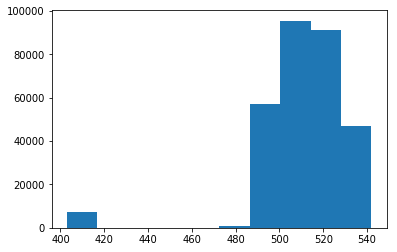
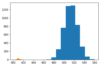
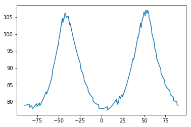
(1): The histogram of depth values observed.
(2): Histogram of 2000 samples from the estimated mixture.
Gaussian Mixture Model:
The depth values within the image typically follow a bimodal distribution; a smaller mode for the depth of the object and a larger mode for the depth of the background. This distribution is typically roughly Gaussian, thus we can calssify each pixel using a Guassian Mixture Model to create an image segmentation of object versus background.
We assume the distribution of depth values for the object are i.i.d. and follow the mixture of two Gaussians, where one Gaussian corresponds to the object and the other to the background. Let \(v_{ij}\) be the observed value at \((i,j)\), we then maximize our likelihood over possible mixtures of two Gaussians. $$\max \limits_{\phi_o, \phi_b, \mu_o, \mu_b, \sigma_o, \sigma_b} \prod_{i,j} p(v_{ij}) \; : $$ $$p = \phi_o \mathcal{N}(\mu_o, \sigma_o) + \phi_b \mathcal{N}(\mu_b, \sigma_b)$$ $$\phi_o + \phi_b = 1, \; \phi_o \geq 0 , \; \phi_b \geq 0$$ This problem can be solved within very few iterations of Expectation Maximization implemented in Scikit Learn (we found 10 iterations to be consistent). Also, while our assupmtions of the depth values being i.i.d. worked in practice, it is a strong assumption, and future work may explore using conditional probabilities or connectivity for classification.
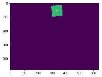
(1): Low pass of the depth map.
(2): Resulting segmentation (green is object, purple is background) and center of mass (yellow).
Segmentation and Center of Mass:
Once we converge to a viable mixture, we can use it for classification. First, we low pass the image to remove high frequency noise and soften the edges. We found this led to cleaner segmentations than classifying on the original image. To low pass the image, we used a Gaussian Blur from OpenCV. We then use our converged mixture model to classify each pixel independently.
Let \(\phi_o^*, \phi_b^*, \mu_o^*, \mu_b^*, \sigma_o^*, \sigma_b^*\) be the optimal parameters to the mixture optimization problem. Our object's depth values should be smaller than the depth values of the background, so without loss of generality let \(\mu_o^* \leq \mu_b^*\). Defining \(p_o = \mathcal{N}(\mu_o^*, \sigma_o^*)\) and \(p_b = \mathcal{N}(\mu_b^*, \sigma_b^*)\), we clasify a pixel value \(v_{ij}\) using the function $$f(v_{ij}) = \begin{cases} 1 \; \; \; \; \; \; \; \phi_o^* p_o(v_{ij}) \geq \phi_b^* p_b(v_{ij}) \\ 0 \; \; \; \; \; \; \; \phi_o^* p_o(v_{ij}) < \phi_b^* p_b(v_{ij})\end{cases}$$ To find the center of mass of the object, we first assume the object has uniform density. Letting the normalization of the segmentation be a joint probability distribution over the indices, the center of mass is then the expected index. $$\begin{bmatrix} c_x \\ c_y \end{bmatrix} = \frac{1}{\sum_{i,j} f(v_{ij})}\sum_{i,j} f(v_{ij}) \begin{bmatrix} i \\ j \end{bmatrix}$$
If the object is predicted to be strangely large or small, the observation is ignored and no action is performed. Otherwise, this center of mass is passed to the controller to move the end-affector of the Sawyer (more details below).
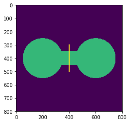
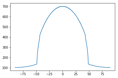
(1): Synthetic dumbell (green) with the angle our algorithm would grasp at.
(2): Plot of the objective function w.r.t. theta. Optimum is achieved at \(\theta = \pm \frac{\pi}{2}\).
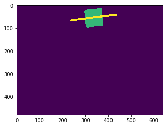
(3): Real box (green) with grasp angle (yellow).
(4): Plot of the objective function w.r.t. theta. Optimum is achieved at \(\theta \approx \frac{\pi}{25}\).
Grasp Angle:
Because our gripper was the parallel gripper, adapting to specific objects mainly required determining at which angle to grasp the object.
First we continue to assume the object has uniform density. We make an additional assumption that the object is simply connected. We then center the grasp above the detected center of mass, as this would balance the mass on either side of the gripper.
Before lowering the end-affector, we determine an angle to rotate the gripper by. We approached this problem using a heuristic and approximating a corresponding optimization problem. When picking up objects that are uniform density, a natural approach would be to grab the object around the plane passing through the center of mass that minimizes the cross sectional area. For example, a human picks up a dumbell around the small cylinder connecting the two large pieces, as opposed to across the ends of the two large pieces. We now formalize a way to solve for this heuristic.
First, we define the indicator function \(f: \mathbb{R}^2 \rightarrow {0, 1}\) that is centered at the center of mass (center of mass corresponds to \((0,0)\)) where \(f(x,y) = 1\) if the object occupies \((x,y)\) and \(f(x,y)=0\) otherwise.
A line passing through the origin at angle \(\theta\) is then defined as $$\mathcal{L(\theta)} = \left \{ (t \cos \theta , t \sin \theta) \; | \; t \in \mathbb{R} \right \}$$ Our goal is to find a line passing through the origin that minimizes the intersection of the line and the object. Thus, our optimization problem is $$\theta^* = \argmin \limits_{\theta \in \left [\frac{-\pi}{2}, \frac{\pi}{2} \right]} \int_{-\infty}^{\infty} f(t \cos \theta, t \sin \theta) \text{d}t$$ The objective function is \(\pi\)-periodic, allowing us to restrict the domain. In general, the objective function is not convex on \(\theta\). However, for reasonable applications, grid search is effective at finding a close to optimal solution. Additionally, if the object is a convex set, the objective function is Lipschitz-continuous on \(\theta\) allowing for a theoretical guarantee of obtaining the optimal solution using bisection method. Using Scypy's integration capabilities, this integeral can be computed rather quickly.
After having found an angle to grasp at, the end-affector is rotated by that angle and then lowered to the object. For objects that aren't simply connected (such as a donut), this algorithm might have a harder time as it would attempt to grasp around the entire object as opposed to using the holes in the object to its advantage. This is an area we hope to explore more in the future.
Controller
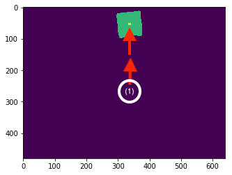
(1): the initial scan position (approximate)
The principle challenge our controller had to solve was that of converting the dx,dy in the image (measured in pixels) to a dx, dy in the real world, measured in meters. We noticed that the images freenect (our open Kinect interface) produced were created based on the following rule:
the value at pixel (i,j) corresponds the distance that point is in the real world from the sensor, in millimeters
We interpreted this rule to mean that the images were in some way processed to have a useful structure, and then tuned our controller constant to take as input the dx,dy (pixels) and output dx,dy(meters), which we found to work well experimentally
If this controller ended up not working, we considered decaying our controller constant harmonically but this presented the tradeoff that we would not be able to move the object on the workspace after execution began, because the constant would have already decayed. We also considered using a PID controller, but found that the added complexity was not necessary here
System Diagram
Results
Final Product
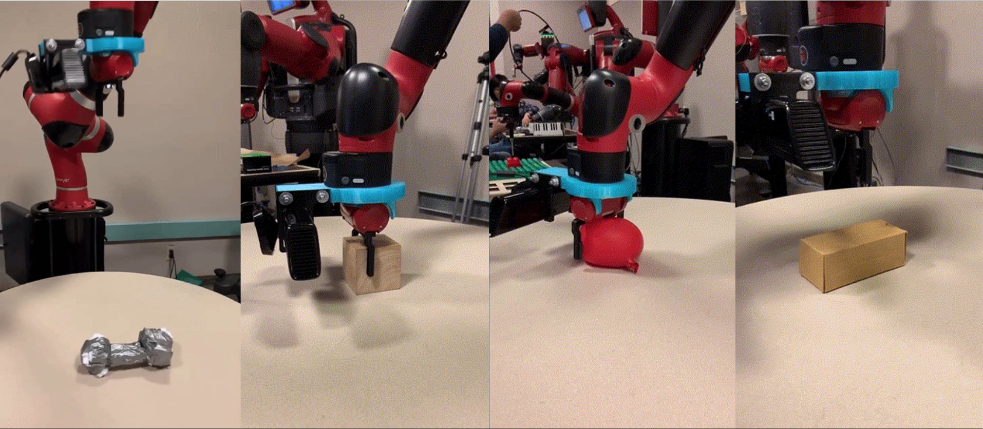
Putting everything together, our system is able to perform robustly in grasping and lifting a variety of objects. Upon testing on different shapes and positions for objects, we found that our system was able to reliably locate, actuate to the correct position, rotate to the correct orientation, and grasp the object on several iterations. In practice, we saw that regardless of the amount of synthetic (sometimes adversarial) movement/rotation of the object, our system was able to use the designed controller in order to perform its task and find and grasp the object. In order to test the various aspects of our system, and to test the robustness along each axis of our goal, we present scenarious below in which the system is robust to a different category of difficulty, and what it must have done correctly in order to achieve a proper grasp.
Conclusion
In terms of the final product we were able to deliver, our solution was able to meet the design criteria we first posed, and was able to go above and beyond in terms of what we set out to accomplish. In particular, one of our main goals of this project was to create a system that was able to grasp not only just a few classes of objects, but a system that was able to attempt and successfully grasp general objects in a variety of orientations and sizes given a few, reasonable constraints.
Our initial design of using the Kinect mounted onto the wrist of the Sawyer also proved to be a good design choice as our image processing pipeline was able to take advantage of the depth data and produce results that were able to reliably provide location and rotation data to our actuation system.
There were many difficulties we encountered throughout the process, but two of the major difficulties were not being able to use the Reflex Takktile Gripper and sensing of objects of nonhomogeneous height. Early on, we had many problems with the Reflex Takktile Gripper in terms of API usage and connectivity, and making the decision to change to the parallel grippers was a huge design decision as we lost much of the data that would be accompanied with the Reflex Takktile Gripper, but also were using an API that was simpler to use and understand. A future goal of this project would definitely be to include the Reflex Takktile Gripper and the data that comes with it. The other problem of sensing objects of nonhomogeneous heights was one that we saw with objects like the Lego block. Because of the way our sensing system is designed, objects which had clear two or three levels of height to them were difficult to work with. Another future goal would be to redesign the sensing system so that it is robust to these types of object.s
Our final product contains only a few slight "hacks" depending on the perspective. One is that we use a hardcoded, thresholded value for our sensing pipeline in order to find the difference between the object and the table. In order to this, we can change the sensing system so that it uses a different metric for determining the difference between the object and the table. The other "hack" is that we use a simple box constraint that is the height of the size of the Kinect in order to prevent the Kinect from colliding with the table by constraining the motion plans returned from MoveIt IK. To address this, we can manually change the URDF of the Sawyer to include the dimensions of the Kinect as part of the end effector itself and then remove the box constraint as MoveIt would now remove the motion plans that cause the robot from hitting itself (since the Kinect would effectively be a part of the Sawyer schematic).
About Us
Hank
About
I'm a third year EECS major who's interested in distributed systems, machine learning, and image processing. I was born in Seattle, and recently have picked up an interest in hiking during my free time. Over the summer, I'm also a big fan of swimming. I'm a bit of a foodie (but it has to be vegetarian or seafood, I'm a pescatarian), and a fun fact about me is that I own a Sous Vide machine, though I haven't gotten much of a chance to use it during the semester.
Contributions
I measured, designed, and 3D printed the parts for the Kinect interface. This website borrows heavily from the styling and general formatting from my personal website, which we used for this project because we weren't huge fans of the default templates. I also wrote the code we used to interface with MoveIt, and contributed to a variety of small miscellaneous things as they came up.
Arsh

About
I'm a third year EECS major who's interested in Mathematics, Machine Learning, and Signals. I was born in Ney York City but grew up in Burbank, California for most of my childhood. My passions include sketching, painting, gymming, and writing music. I also really love reading about math!
Contributions
I mostly worked on designing, formalizing, and implementing our image pipeline to localize objects and determine grasping angles. I also contributed to the design choices for constraints versus generalizability and assisted with integrating the image pipeline into the controller.
Arjun
About
I'm a third year Computer Science major who's interested in signals processing, computational neuroscience, and machine learning. I was born in a small town called Hillsborough in New Jersey and I'm a really big fan of the west coast. I really enjoy taking photos and going on hikes through all the beautiful parks there are in California (we don't have this much beauty back on the east coast). I also draw and play tennis in my free time.
Contributions
I worked mainly on helping design and implement the controller and various design decisions regarding the movement of the robot in certain situations, and I wrote code to interface with MoveIt and for the different constraints on the arm during the various stages of execution. I also helped to fine-tune parameters such as that for the static transform and the ones for conversion between the pixel to analog domain.
Additional Content
CAD Models: (all .step)
(downloads may not work on Chrome)
Our Code:
Other Videos
Miscellaneous
- Our presentation
- We used freenect as our Kinect API, you can find it here